The Numato Opsis board includes two CMOS crystal oscillators connected to the FPGA and one crystal connected to the Ethernet interface.
For details about the crystal connected to the Ethernet interface, please see the Ethernet page.
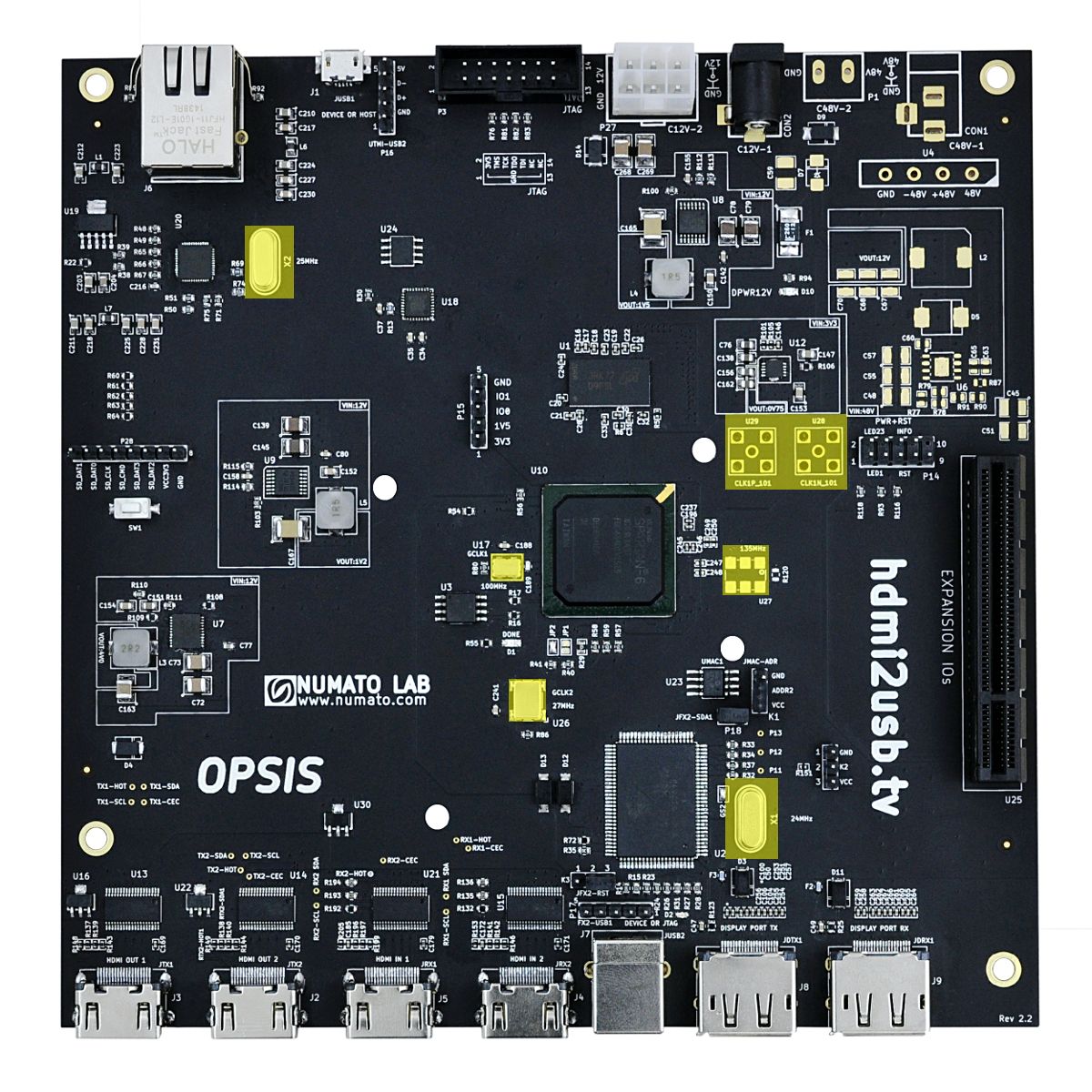
Clock Layout
- Clock related sections are highlighted in Yellow
FPGA Clocks
100MHz Clock
This clock is the primary clock for the FPGA.
| Specification | |
|---|---|
| Frequency | 100 MHz |
| Schematic Sheet | SPI.sch |
| Schematic Reference | U17 |
| IO Standard | LVCMOS33 |
| Part | FXO-HC536R |
| Clock Net Name | USRCLK |
| Clock FPGA Pin | AB13 |

27MHz Clock
This clock is used for generating the 81MHz or 135MHz clock signal needed by the GTP for interfacing with DisplayPort.
See the GTP transceiver page for details about how to use this clock.
| Specification | |
|---|---|
| Frequency | 27 MHz |
| Schematic Sheet | SPI.sch |
| Schematic Reference | U26 |
| IO Standard | LVCMOS33 |
| Part | CB3LV-3I-27M0000 |
| Clock Net Name | 27Mhz |
| Clock FPGA Pin | N19 |

Spartan 6 Clocking Resources
The Spartan 6 on the Numato Opsis contains 4 clock management titles (CMT). Each CMT contains a single Phase Lock Loop (PLL) and a two Digital Clock Managers (DCM).
The small number of clocking resources can be a major factor in restricting which features can be used at the same time with the PLLs being the most important.
Generally,
2 x PLLs are used for the HDMI inputs (one each) to regenerate the pixel bit clock from the pixel clock.
1 x PLL is used for the GTP transceivers.
1 x PLL is used for generating the system clocks.
Full details about the Spartan 6 clocking resources can be found in the Spartan-6 FPGA Clocking Resources User Guide (UG382).
