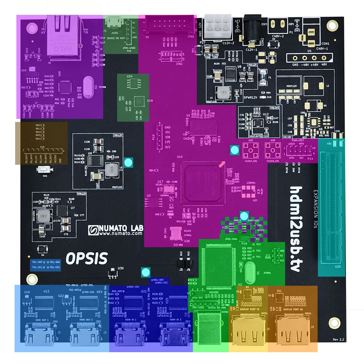
Layout
Board Layout
- FPGA & Memory - Highlighted in Pink
- Video
- DisplayPort (GTP Transceivers) - Highlighted in Yellow
- HDMI - Highlighted in Blue
- Connectivity
- Ethernet - Highlighted in Purple
- USB - Highlighted in Green
- Expansion
- TOFE - Highlighted in Aqua
- SD Card - Highlighted in Brown
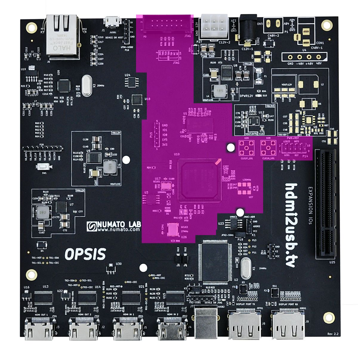
FPGA & Memory Layout
- FPGA & Memory section is highlighted in Pink
Video Layout
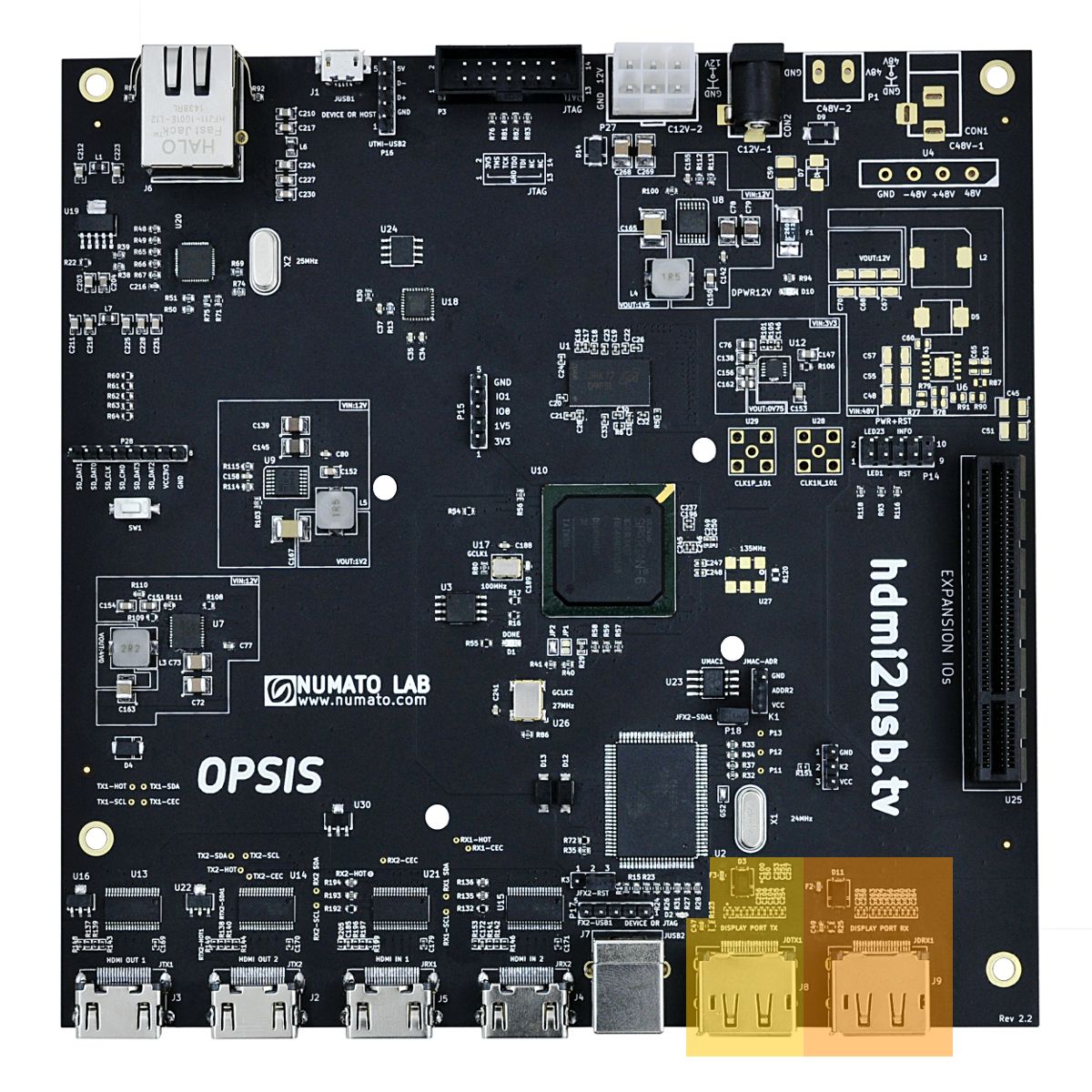
DisplayPort (GTP Transceivers) Layout
- DisplayPort (GTP Transceivers);
- Receiver (RX) is highlighted in Dark Yellow
- Transmitter (TX) is highlighted in Light Yellow
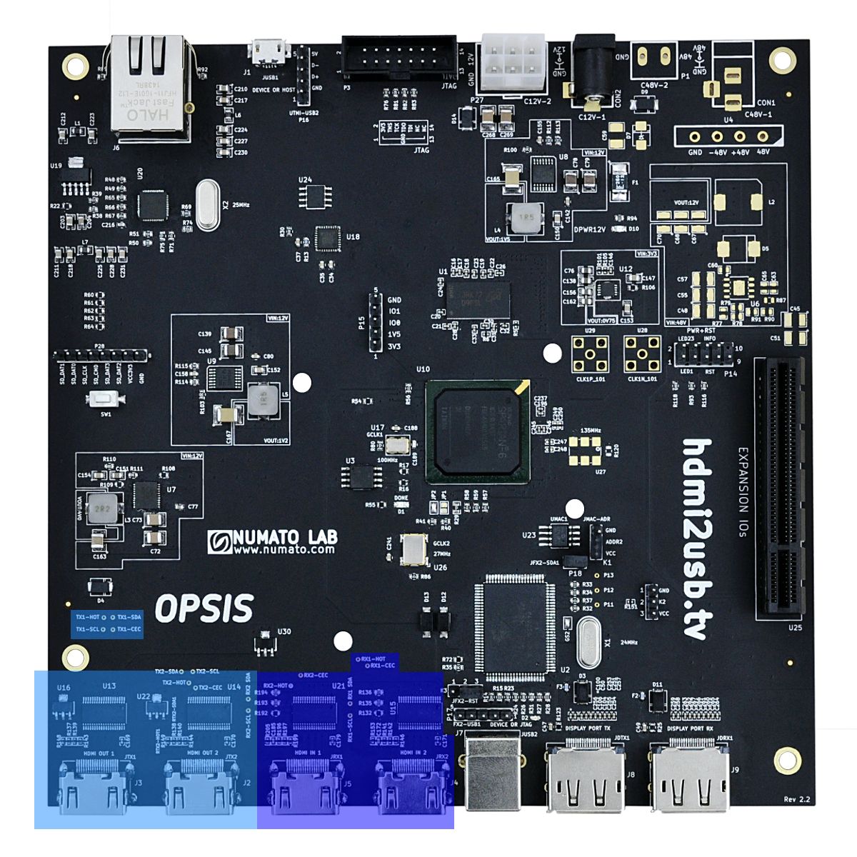
HDMI Layout
- HDMI;
- Receiver (RX) is highlighted in Dark Blue
- Transmitter (TX) is highlighted in Light Blue
Connectivity
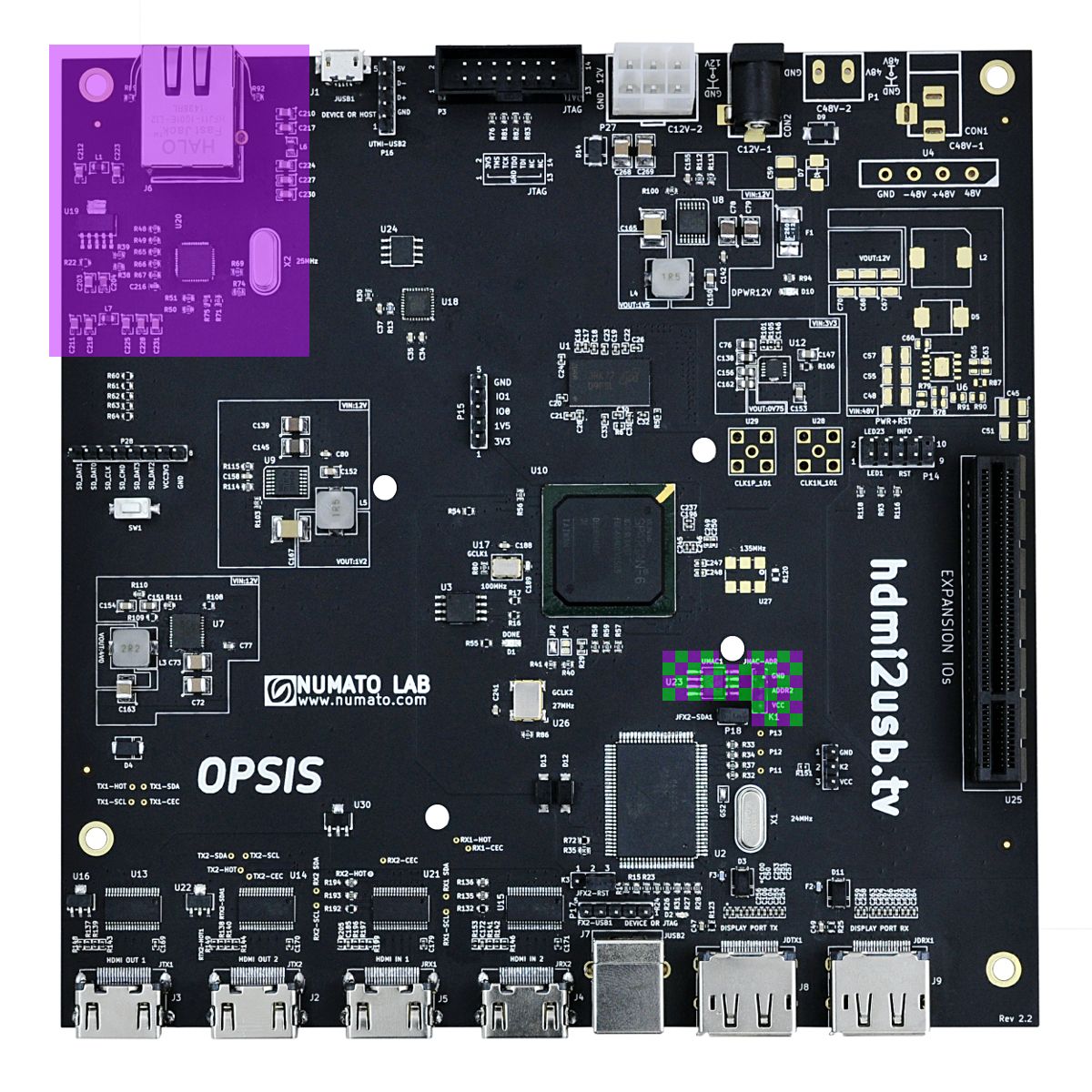
Ethernet Layout
- Ethernet is highlighted in Purple
- Parts shared between Ethernet and USB Peripheral are highlighted in a checkerboard fashion.
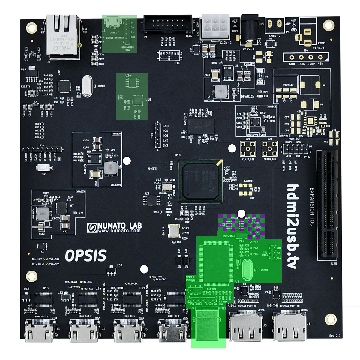
USB Layout
- USB;
- USB OTG (Host or Device) is highlighted in Dark Green
- USB Peripheral (Device Only) is highlighted in Light Green
- Parts shared between Ethernet and USB Peripheral are highlighted in a checkerboard fashion.
Expansion Layout
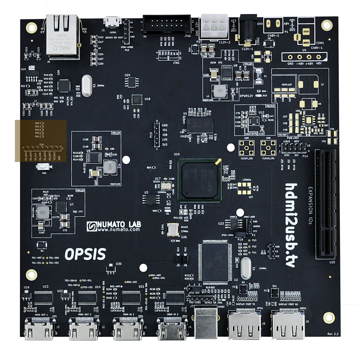
SD Card Layout
- SD Card is highlighted in Brown
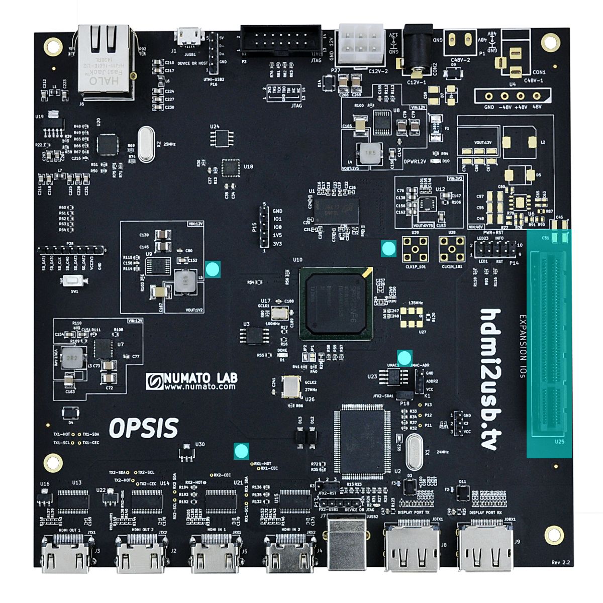
TOFE Layout
- TOFE is highlighted in Aqua
Config & Status Layout
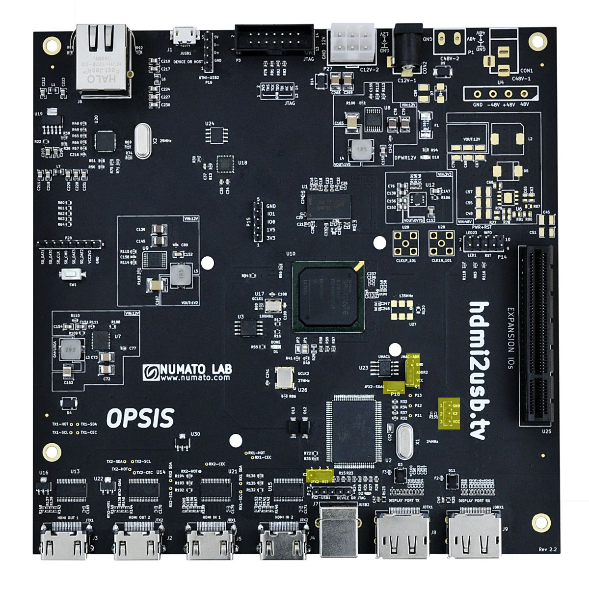
Jumper Layout
- Jumpers are highlighted in Yellow
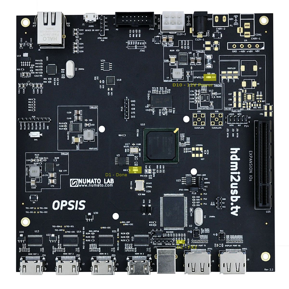
LEDs Layout
- LEDs are highlighted in Yellow
Supporting Component Layout
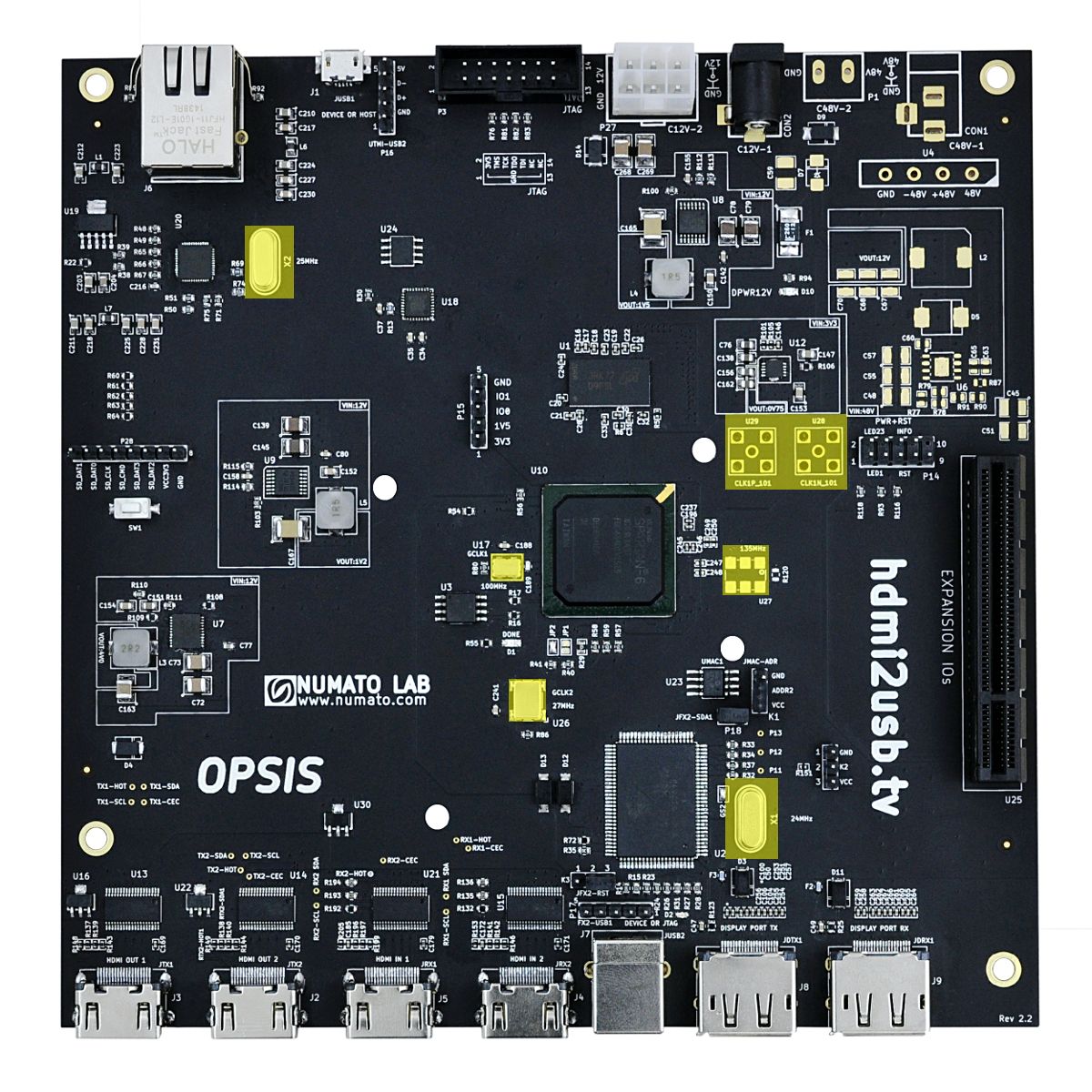
Clock Layout
- Clock related sections are highlighted in Yellow
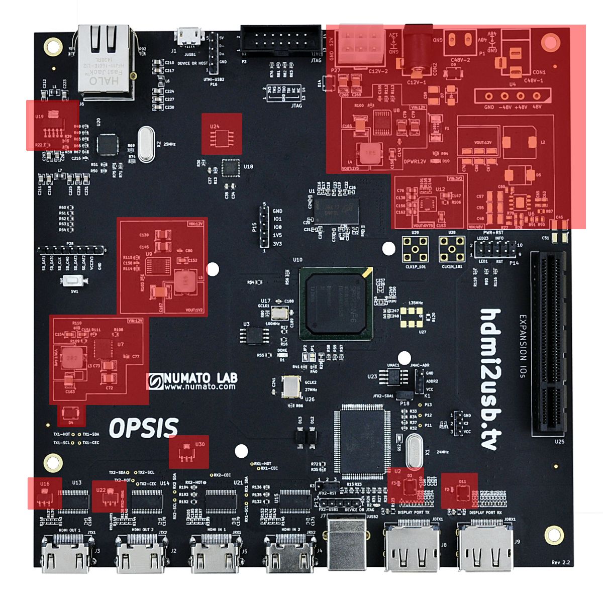
Power Layout
- Power related sections are highlighted in Red