Power Supply
The primary power supply for the Opsis board is 12V DC.
The board can draw up to 2 Amp under extreme conditions but will normally draw significantly less.
TOFE expansion boards are also directly connected to this 12V supply which can increase the current requirements.
Summary
- Minimum: 12V DC @ 2A (24 Watts)
Connectors
There are two power supply connectors on the Opsis board.
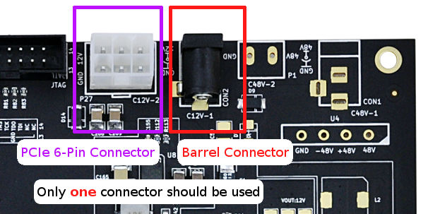
Only one power supply connector should be used at once.
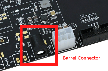
Barrel Connector

| Specs | |
|---|---|
| Labelled | Con2 |
| Inner Diameter | 2.0mm |
| Outer Diameter | 5.5mm |
| Inner Pin | +12V |
| Outer Shield | GND |
PCIe 6-Pin Connector
| Specs | |
|---|---|
| Labelled | C12V-2 |
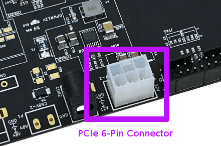
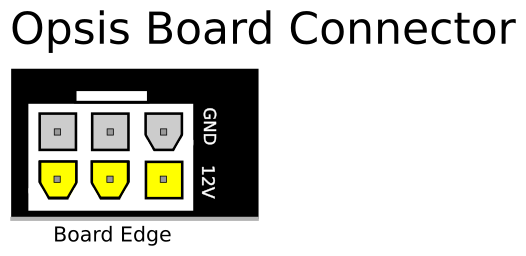
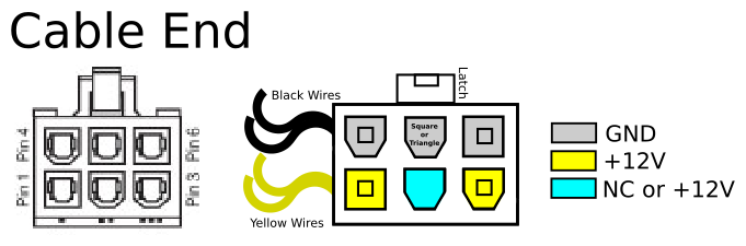
The Opsis can be powered by PCI Express connector from an ATX power supply. Sometimes called the "Graphics card connector".
These connectors should have yellow and black wires going into them. Make sure black wires are on the side with the clip.
There are a number of power connectors which look similar to the PCIe 6-Pin which are not compatible with the Opsis board and can damage your board!
Do not try to use Opsis board with;
- 6 Pin ATX Auxiliary power connector (which has orange and red cables).
- 8 Pin EPS connector (which has yellow and black cables).
- 4 Pin ATX 12V connector, also called "CPU Power" (which has yellow and black cables).
Extra Details
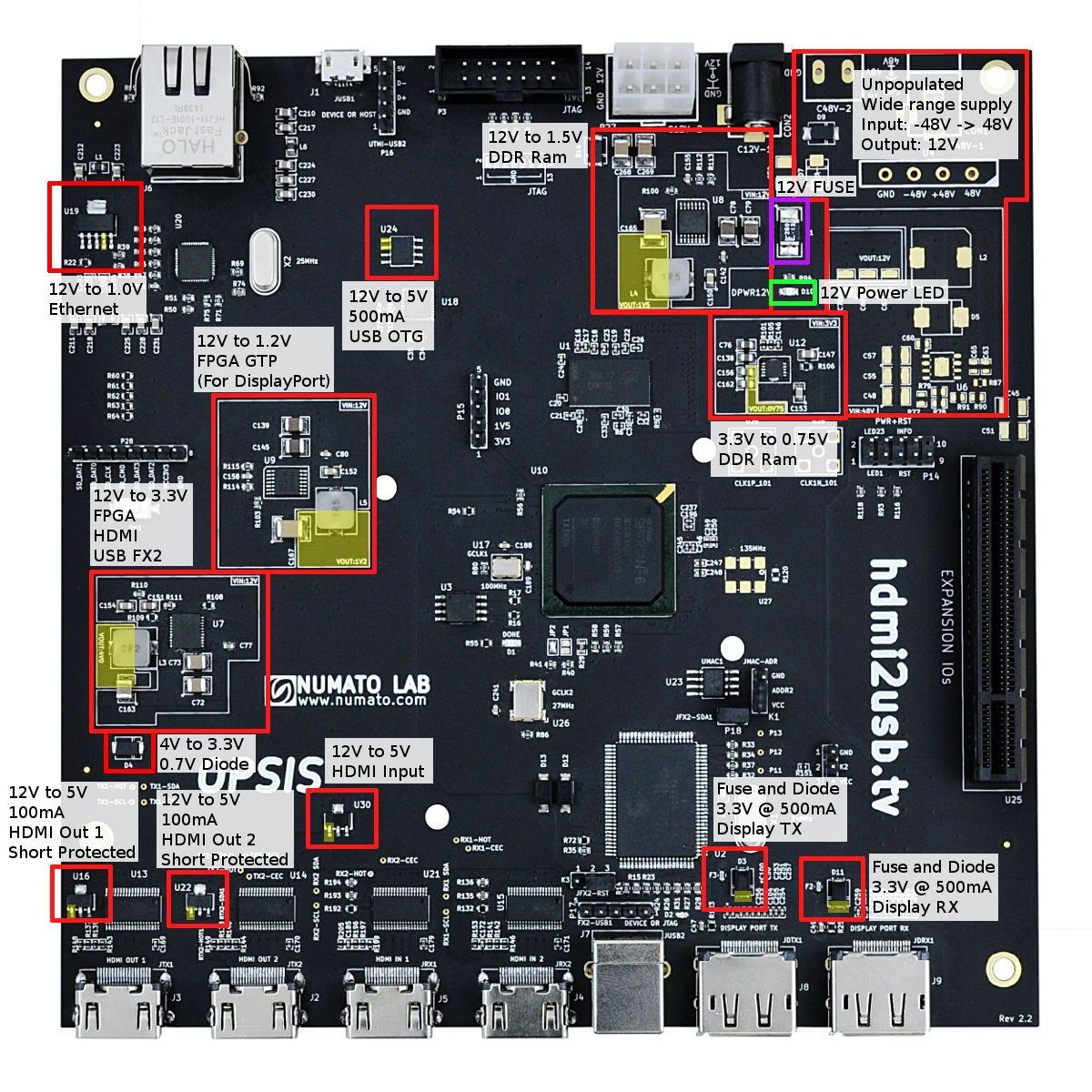
The 12V supply is not used directly by the board, instead converted to the various voltages needed by the ICs.
There are numerous power converters on the board. These are highlighted in the following diagram;
- The output of each supply is highlighted by the yellow area.